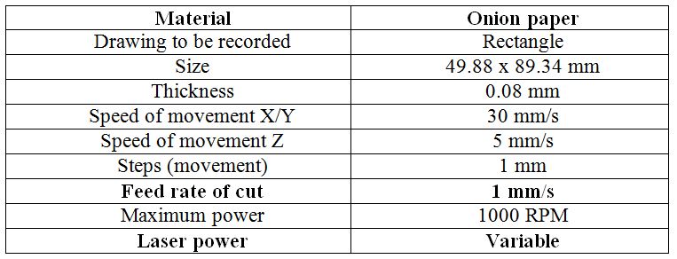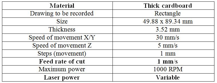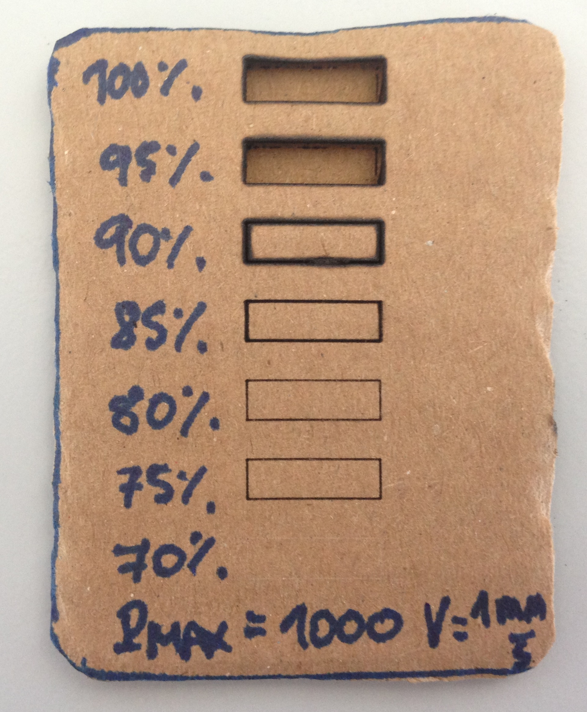
In this tutorial an example of engraving in cardboard is made for the following parameters.
HARDWARE
We make sure that the jumper is in the correct position and we connect the USB data cable to the controller board and to our PC as well as the power supply of the cutter.
SOFTWARE
We start the LaserWeb software by entering the command window, located in the directory C:LaserWeb3 and run the command node server.js that will give us the URL to which we must access in Google Chrome. At this point it is very important not to close the command window so that we can use the software. In addition, we can see the Gcode commands that are sent to the machine during the engraving process.
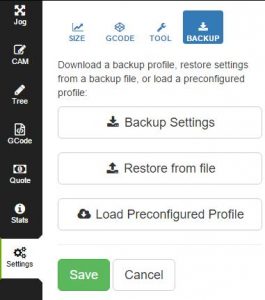
Now, we load the configuration profile that is offered along with the manual laserweb-settings-backup.json. To do this, go to Settings/Backup/Restore From file and select the previous file. We then save and refresh the page for the changes to be updated.

Once this is done we connect the USB port together with the Baud-rate. By default, you have a baud rate of 115200. If everything went well, the message opens: COMx where x is the associated port number.
Before to engraving, it is necessary to define the reference point with the home laser button by moving the machine axes to the lower left corner. Once this is done, click on the Set zero button and the reference point is already defined. This way, every time you click on home laser will go to this point and the same thing happens every time a new engraving is done.
The image to be recorded is then loaded, which appears in the CAM menu and can be resized by SVG Resolution. The actual size of the image to be recorded appears in mm on the same image. When the size and position are suitable we can enter Generate Gcode code. At this point it is important to see if the image is in SVG or not since in this format we will have the image as a vector and the outline will be recorded. On the contrary the image will be recorded line by line filling the colors of the image. It is recommended that the image be converted to vector, option that implements the same software. The code Gcode that is sent to the machine can be observed in the menu Gcode.
In order to perform the engraving, a laser intensity of 100% and a movement speed of the axes of 30 mm/s in the XY plane and of 5 mm/s in the Z axis have been defined, although the latter will not be used to record in 2D. Movement steps that have been set to 1 mm. In addition, it is advisable to check that the area of engraving is desired by clicking on the button check outline.


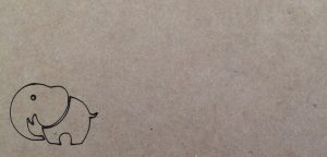
Done this, just load the Gcode code by clicking on START and the result is the following:
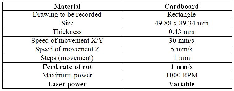
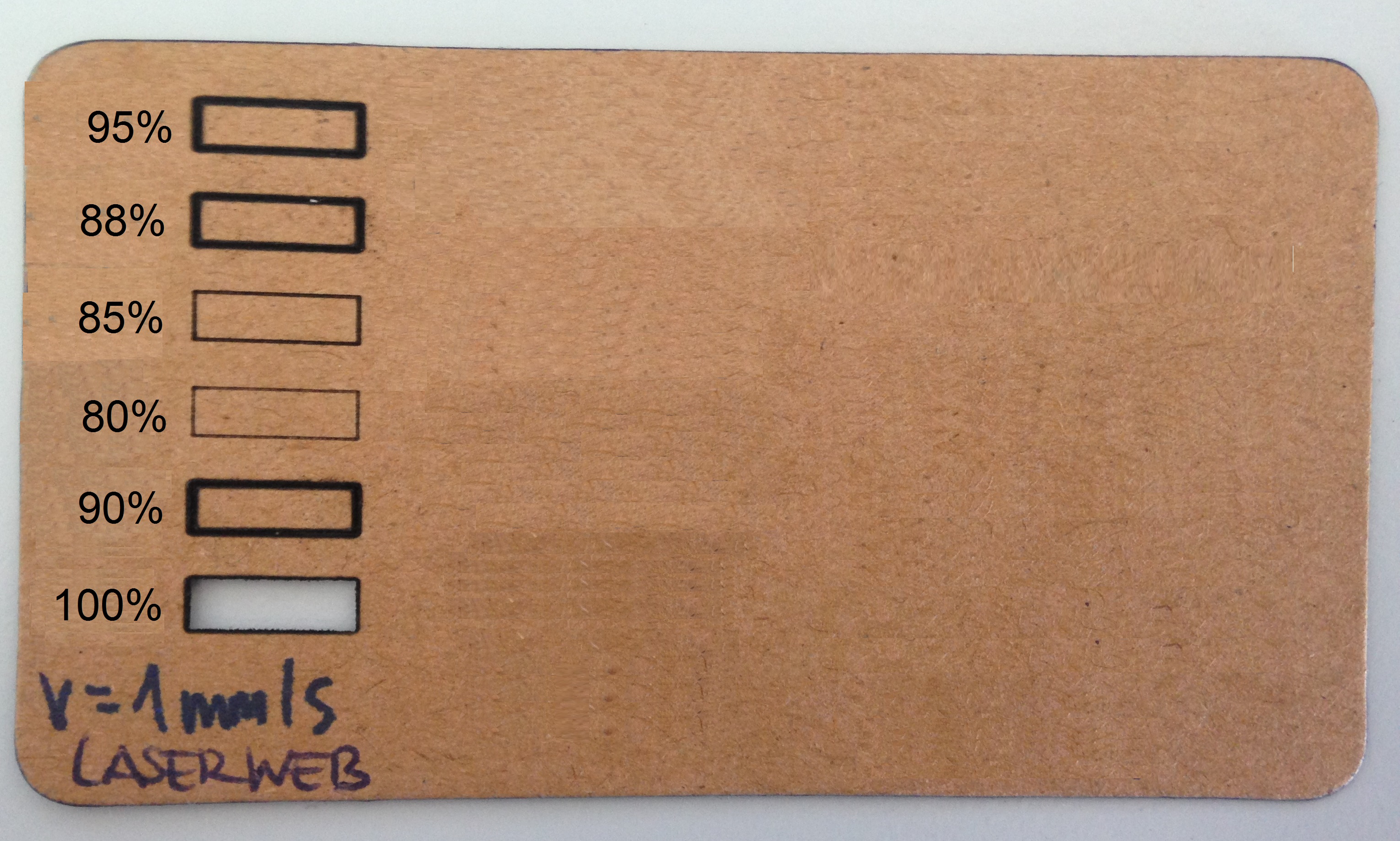
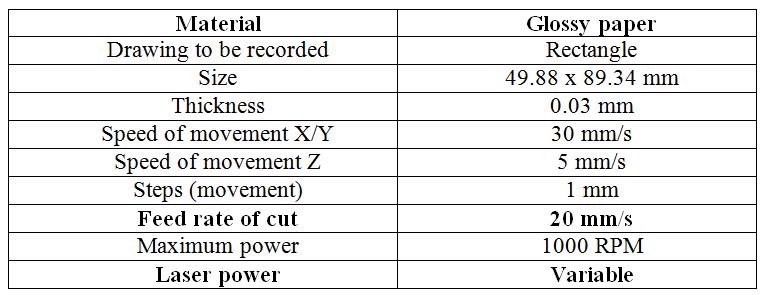
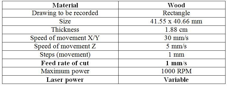
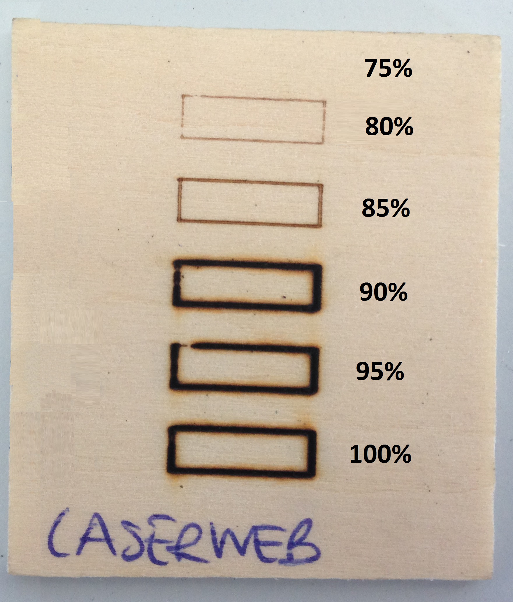
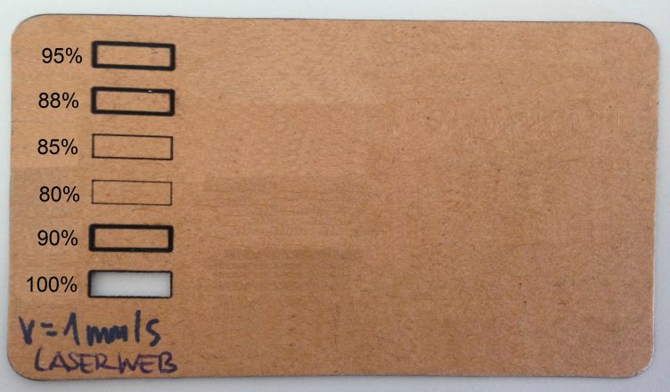
Finally we attach the calibration sample made for different engraving modes and materials. LaserWeb allows us to record with different powers of the laser indicating the percentage of use of its maximum power. This will allow us to record more or less intensity on the material even cut it. Therefore, a sample is made for a maximum laser power of 1000 RPM, so we will move in the corresponding [10, 1000] RPM range with 1% and 100% of the maximum power. In some materials for maximum power it is not possible to cut even record the desired image. This is why it is necessary to vary the feed rate of the cut, set by default to 20 mm/s.