Rotor Controller Unit
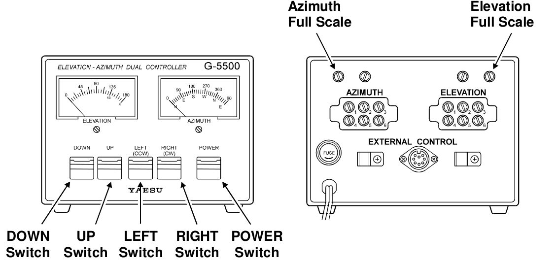
The rotator of the Wimo X-Quad antennas is remotely operated from the ground station laboratory with a controller unit. This controller unit incorporates elevation (from 0º to 180º) and azimuth (from 0º to 450º) indicators. The azimuth is displayed both in degrees and in cardinal coordinates.


The controller unit has also four switches which allow the manual operation of the rotator. However, the usual operation will be made by a tracking software installed in a computer. Direct connection between the controller and a common PC port (i.e. USB, RS-232, etc.) is not possible, but an interface attached to the external control connector of the controller will provide RS-232 connectivity.
Las Vegas Boulevard Tracker
The GS-232A Computer Control Interface, supplied by Yaesu as well, is the most straightforward device to control the rotator digitally from a PC. However, a lower cost and open source design has been chosen for the GranaSAT project: Las Vegas Boulevard Tracker (LVB), designed by Howard Long G6LVB, and originally presented at the 2003 AMSAT-UK Colloquium.

The LVB is attached to the external control port of the rotator controller as follows:

-
Pin
Function
6
Provides 2 to 4.5VDC corresponding to 0 to 450° 1
Provides 2 to 4.5VDC corresponding to 0 to 180° 4
Connect to Pin 8 to rotate left (counterclockwise) 2
Connect to Pin 8 to rotate right (clockwise) 5
Connect to Pin 8 to rotate UP 3
Connect to Pin 8 to rotate DOWN 7
Provides DC13V to 6V at up to 200mA 8
Common ground
Once the LVB is attached, a warning message will appear on its LCD screen, indicating that a calibration must be performed before the correct elevation and azimuth values of the rotator are displayed.

After the calibration process, the same elevation and azimuth values as the ones marked on the analogue indicators of the rotator controller are displayed on the screen of the LVB and they are accessible from the RS-232 port of the PC. In addition, it is also possible to send commands to the LVB from a terminal or from a satellite tracking software and aim the antennas to a certain direction.

PCB Design (LVB Tracker)
The PCB was manufactured with the LPKF S63. The original design was imported in ALTIUM

Altium SCH file

Altium PCB file

Circuit Cam 5.0 file

Programming fuses (Remember disabling the Watchdog)
and the ALTUIM Project LVB Altium Project and original Firmware hex file LVBTrack.hex
Standard GS-232 commands supported
- C Return azimuth
- C2 Return azimuth and elevation
- Maaa Set azimuth to <aaa> (Firmware 0.7 and above)
- S Stop rotator
- Waaa Set azimuth to <aaa>
- Waaa eee Set azimuth and elevation to <aaa> and <eee>
Extended GS-232 command set supported
- FAE Set 360º azimuth calibration
- FAF Set 450º azimuth calibration
- FAMm.mm Set azimuth multiply parameter to <m.mm>
- FAOooo Set azimuth offset parameter to <ooo>
- FAS Set 0º azimuth calibration
- FEE Set 180º elevation calibration
- FEMm.mm Set elevation multiply parameter to <m.mm>
- FEN Set 90º elevation calibration
- FEOooo Set elevation offset parameter to <ooo>
- FES Set 0º elevation calibration
- FN Set North CCW stopping rotator (default)
- FS Set South CCW stopping rotator
- FW Write calibration parameters to EEPROM
Easycomm commands supported (Firmware 0.7 and above)
- AZaaa.a (integer part only used)
- ELeee.e (integer part only used)
- UPnnnnnnnnnn mmm (ignored)
- DNnnnnnnnnnn mmm (ignored)
