
GranaSAT I Ground Station Equipment
The ground station of the GranaSAT-I will be located on top of the Science Faculty of the University of Granada. It will be responsible for receiving and transmitting data from and to the satellite.
On the first phase, a voice communication with the ISS (International Space Station) will be established. The Amateur Radio on the International Space Station (ARISS) [link: http://ariss.rac.ca/oindex.htm] is the international working group which regulates these contacts with the ISS.
There exist two possible communication procedures. Telebridge contacts are performed via a dedicated ARISS amateur radio ground station and thus avoiding the necessity of deploying a ground station. But at the same time, the learning possibilities for students at the university would be suppressed and the ground station would not be available for future steps in the GranaSAT-I project.
The second possibility, Direct contact, will be the selected one. The installation requirements are defined by theAmateur Radio on the International Space Station (ARISS). As it can be observed in the next diagram, a duplicated system will have to be set up, with one prime station and one backup station:
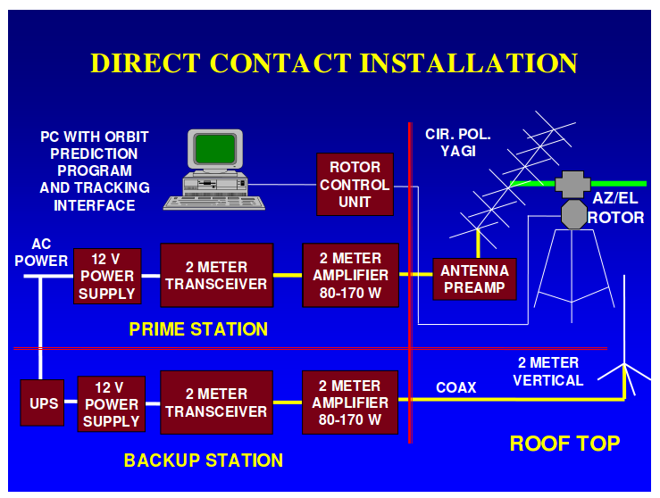
The frequencies in use are the following:
*Voice and Packet Downlink: 145.80 (Worldwide)
Voice Uplink: 144.49 for Regions 2 and 3 (The Americas, and the Pacific)
Voice Uplink: 145.20 for Region 1 (Europe, Central Asia and Africa)
*Packet Uplink: 145.99 (Worldwide)
Crossband FM repeater downlink: 145.80 MHz (Worldwide)
Crossband FM repeater uplink: 437.80 MHz (Worldwide)
Worldwide SSTV downlink: 145.800 MHz
Therefore, the duplicated antennas system will operate in the 144MHz and 430 MHz range frequencies, achieved by 5λ/4 antennas respectively (λ=2m / 70cm) .
A few considerations are to be taken into account in order to choose a suitable material for satellite communications, which are already well known and standardized in a mature aerospace industry.
Remarkably, the polarization of the traveling waves will be a key issue. Linearly polarized waves traveling in presence of a magnetic field (i.e the planet magnetic field) are subject to the so called “Faraday rotationâ€, which will cause a certain direction of polarization to change into another. A polarization loss will take place if the receiver is polarized on a certain direction (according to the expected wave polarization) but the latter has changed due to the Faraday Rotation.
In addition to this, operating frequencies have to be such that the waves are able to go through the different layers of the atmosphere without being reflected. Reflexion avoidance is achieved with higher frequencies (in many satellite communications, in the order of GHz) but the amateur frequency used by ARISS satisfies this need as well, with the advantage of no frequency license costs.
A detailed description of the equipment is given below:
Wimo X-Quad 144MHz / 430MHz antennas
Their cross structure (as shown in the pictures) allows to minimize the polarization loss, as they can receive whether in vertical or horizontal polarization without any additional reconfiguration.
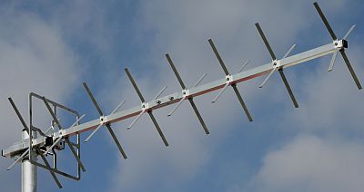
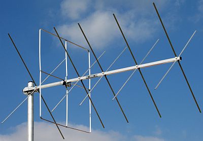
Technical details for both 70cm and 2m antennas are shown in the table below:
-
2m X-Quad
70cm X-Quad
Elements per plane
12
18
Gain
10.5
12.8
dBD
3-dB bandwidth horiz. (E)
47
36
degrees
3-dB bandwidth vert. (H)
47
36
degrees
F/B ratio
19
21
DB
Max. power
1500
1000
Watt
Length
1460
1270
mm
Hight
730
220
mm
Weight
2.3
1.6
kg
Wind load @ 160km/h (100mph)
74
48
N
Connector
2xN-jack
2xN-jack
Stacking resistance
2.82
1.1
m
Phasing harness for RHCP or LHCP
18047
18049
Part no.
18010
18011
User guides:
http://www.wimo.de/download/xquad.pdf (2m)
http://oz1bxm.dk/sat/Wimo-70cm-Xquad.htm (70cm)
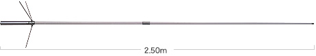
Diamond X-200N Antenna
This is a vertical antenna with coverage of both 2m and 70cm bands. Although crossed-Yagi antennas like the previous ones are the recommended by the ARISS, vertical antenna have also been proved to be able to establish communication with the ISS.
Specifications:
-
Frequency 144-146MHz
Gain 2m 6.0 dB
Gain 70cm 8.0 dB
Max. power rating 200W
Max wind resistance 50m/sec
Impedance 50 ohms
V.SWR Less than 1.5:1 (see charts)
Mast diameter accepted 30-62mm
Length 2.5m
Weight 1.5kg
Connector N
Type 5/8 wave two element (2m)
5/8 wave four element (70 cm)
User guide: http://www.radiomanual.info/schemi/ACC_antenna/Diamond_X50-X200_user.pdf
70cm / 2m X-Quad circular pol. emphaser
In addition to the simultaneous vertical and horizontal linear polarization achieved by the antenna construction itself, circular polarization emphasers will allow both right and left handed circular polarization, which is the one used by ARISS in order to reduce polarization losses.
Yaesu G-5500 antenna rotator
The rotator provides the antennas with the capacity to orientate towards a desired direction (i.e. a satellite moving on the sky in its orbit). The Azimuth Rotator features a turning range of 450°, while the Elevation Rotator has a rotation range of 180°. The model includes an interface jack for computer control, which will allow to rotate and set the correct Azimuth-Elevation directly from a computer in correspondence with a Keplerian Orbit.
Operating manual: http://www.yaesu.com/downloadFile.cfmFileID=994&FileCatID=155&FileName=%2D5500%20Operating%20Manual.pdf&FileContentType=application%2Fpdf
Computer interface manual: http://www.yaesu.com/downloadFile.cfmFileID=820&FileCatID=155&FileName=GS232A.pdf&FileContentType=application%2Fpdf
MFJ-929 Auto Tunner
The MFJ-929 Auto Tunner can automatically tune any coax fed or random wire antenna 1.8 – 30 MHz.
User manual: http://www.mfjenterprises.com/pdffiles/MFJ-929.pdf
Diamond MX-72D Duplexer
This element allows simultaneous operation of the 70cm and 2m bands.
Baluns
This device converts between a balanced signal and an unbalanced signal. The following baluns are used in the GranaSAT ground station:
-
EAntenna Balun 1:4DB1,5 1:4 1,5KW 1.8~54 MHz.
-
Diamond BU-50 Balun 1.2 KW
MFJ-1704 4 Position antenna switching
This component allows to select among 4 antennas or center ground position. It provides the system with a replaceable lightning surge protection.
User manual: http://www.mfjenterprises.com/pdffiles/MFJ-1704.pdf
Mast preamplifiers
Two mast preamplifiers are used in the ground station:
-
SHF Mini2 preamplifier
-
MVV 432/2 preamplifier
MFJ-272N Lightning protector, 1500W PEP