
In this article, we will discuss the SPI protocol, which is fundamental when higher data transfer speeds are required compared to I2C, using one of the most accessible microcontrollers, the ESP32. In this case, the task is performed after securing the main objective: ensuring that the data transfer rate is sufficient for data acquisition through the ADC.
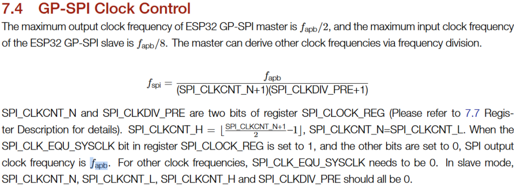
The frequency of the ESP32 is determined by the following expression, where SPI_CLKCNT_N and SPI_CLKDIV_PRE are bits in a register that can be modified to adjust the clock frequency. Therefore, the frequency cannot be arbitrary; it must be an integer value. To achieve a clean 62.5 MHz SPI frequency, the APB bus frequency must be an integer multiple of it, such as 62.5 MHz, 125 MHz, 187.5 MHz, etc.
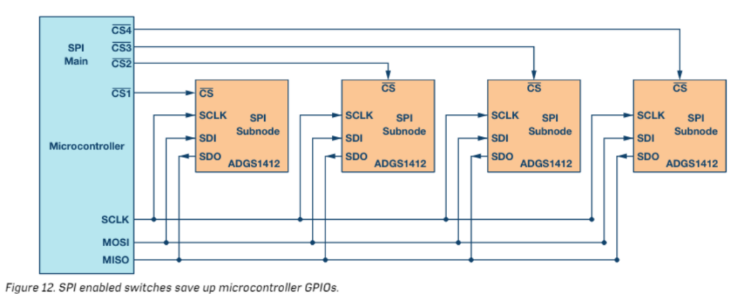
We can use as many peripherals as we want by sharing the MOSI (Master Out Slave In), MISO (Master In Slave Out), and CLK (clock) buses. The CS (Chip Select) pin determines which device we are communicating with, so we need N chip select pins for N peripherals. This digital pin toggles between 0 and 1, signaling to the master which device’s data will be transmitted via the MISO and MOSI buses.
Not all equipment is suitable for observing the high frequency of the latches. For example, with a 4-channel digital oscilloscope like the HAMEG HMO1024 100 MHz, we cannot achieve a low enough time-per-division setting to clearly observe the latches, resulting in the following limitations:
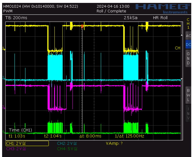
- CS in yellow
- MISO in blue
- MOSI in purple
- CLK in green
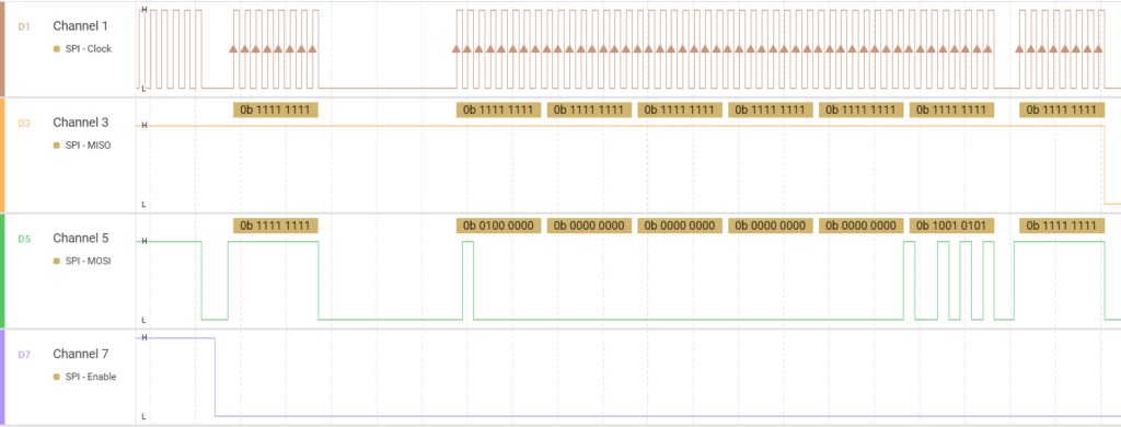
As we can see in yellow the communication starts as soon as I touch the button to save data on the SD card which integrates the 4 buses mentioned above.
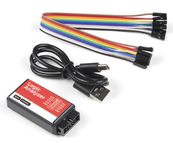
With a USB Logic Analyzer – 24MHz/8-Channel located in Granasat allows us to analyse with the Saleae.Inc software the frequency:
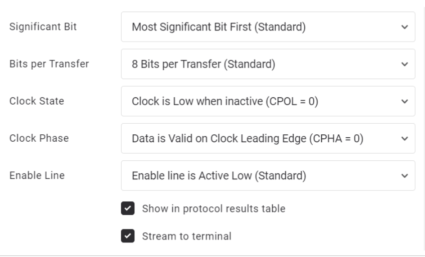
It is important to select the correct SPI mode by configuring the clock polarity and clock phase (there are four SPI transfer modes as we can modify two bits). In my case, I use mode D. Depending on the equipment being used, we need to choose the appropriate mode in the software.
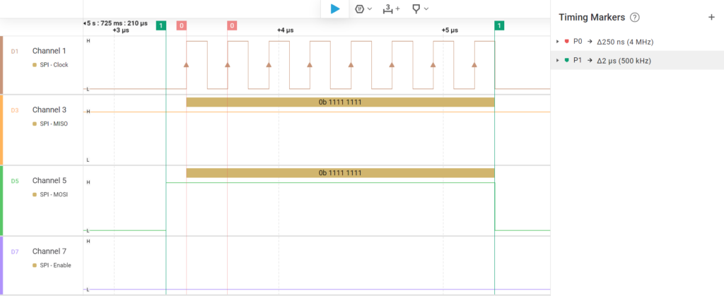
As we can see, the software indicates that the SPI bus clock frequency is around 4 MHz under normal conditions, which is much higher than the 6 kHz that the ESP32’s ADC operates at under typical conditions. Therefore, we will be able to graph in real time what the ADC reads without latency when visualizing the data, allowing our system to work in real time.
Bibliography:
https://www.analog.com/en/resources/analog-dialogue/articles/introduction-to-spi-interface.html