
Introduction
My name is Pedro M. Vallejo Muñoz and I am studing my last year at the University of Granada. The Electrical Power System of GranaSAT is my Bachelor’s Thesis and this website is the way to publish all my progress. Andrés Roldán Aranda is my thesis supervisor and the head of GranaSAT project.Â

This article describes the Electrical Power System (EPS) of the GranaSAT satellite. It shows how the system is designed to collect energy from solar panels, store it in the batteries and distribute it to the charges.
You should be aware of the absolutely difficult characteristics of this mission in order to understand the requirements of this system. The satellite will have some complicated and dynamic conditions, such as a continuous change in the level (low or high) of the batteries, a typical operational range of temperatures (-40 to +80 ºC), vibrations and shocks during the launch and vacuum. You should take into account that everything I have already mentioned is in a space of 100x100x100 mm.
The main purposes of the Electrical Power System are:
- Provide energy to the satellite.
- Store energy.
- Conditioning and distribution.
- Measure voltages, currents and temperatures from differents points of the EPS.
In the following picture you can see a global situation of the EPS in the satellite:

Structure

Solar panels
CubeSats have a limited area in the walls for solar cells because the available area has to be effectively shared with other parts, such as antennas, sensors, cameras, and access port. Typical solar panels for CubeSat consist of two solar cell strings serially wired with no redundancy in case of solar string failure. The loss of electric energy from one solar panel can cause a serious problem due to minimum margin of the picosatellite subsystem power budget.
In the next picture we compare three types of panels:

«Multi-junction (MJ) solar cells are solar cells with multiple p–n junctionsmade of different semiconductor materials. Each material’s p-n junction will produce electric current in response to a different wavelength of light. The use of multiple semiconducting materials allows the absorbance of a broader range of wavelengths, improving the cell’s sunlight to electrical energy conversion efficiency.» (From Wikipedia)
MPPT (Maximum power point tracking)
The power spread out by a panel depends on the temperature, irradiance and the current drawn from the cells. This system is used to obtain the maximum power from the panels.
This system has two parts: controller and actuator. The actuator is a DC/DC converter which changes his dutty-cycle in order to drain the necessary current from the panels. The dutty-cycle is changed by a Microcontroller which has information about the panels (voltages, currents and temperatures).
 Microcontroller
Â
 This system’s part is very critical. The purposes of the digital hardware are to measure currents and voltages of certain points in the system, to communicate with the CPU, to collect housekeeping information and to control the DC/DC converters.
The following requirements for the microcontroller have to be taken into account in order to get a correct system operation:
- I2C-Bus communication line.
- ADC-units have to be available to collect information from sensors.
- Temperature range from -40 ºC to 80 ºC.
- It must be able to start up from solar cell voltages alone (Worst case).
- Pulse-Width-Modulators (PWM) to control the duty-cycle of each converter.
DC/DC Converter
This circuit is connected to the microcontroller. The switcher of the converter is controled by the microcontroller in order to maintain the MPPT. Furthermore, his output is connected to the batteries.
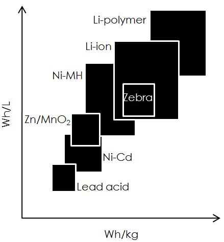
Batteries
If you are a small-satellite developer, you must also consider the issue of energy storage. When the satellite is in view of the sun, the power system uses the available solar energy. However, during periods of solar eclipse, the spacecraft uses the previously stored energy. In the following diagram you can see a comparison of the differents batteries used in spatial missions.
Overcurrent protection
This system will stop the current flow, if a user fails. We will obtain minimize damages and power losses. The implementation of this system will be conformed by current sensors monitored by the microcontroller.
Â